What Materials Are Needed Before a Digital Twin Project?
Continue listing drawings, models, devices, sensor points, APIs and deployment conditions.
A data center digital twin normally does not replace DCIM, environmental monitoring, BMS or EPMS. It aligns sites, rooms, racks, rack units and devices, then connects assets, capacity, power, cooling, alarms and work orders. Before implementation, establish the authoritative source, object IDs, time rules, read permissions, error states and acceptance evidence for each data type.
DCIM commonly handles capacity, assets, energy use and infrastructure management. Environmental monitoring covers temperature, humidity, leaks, smoke detectors, UPS units and air conditioning. BMS and EPMS manage building facilities and electrical power respectively. A digital twin can provide one spatial entry point and link these systems; it should not issue control commands in place of specialist systems without authorization and a safety assessment.
The first list to prepare is therefore not “every API.” Record each system’s responsibility, what the digital twin reads, and which states should link back to the source system for action.
Use consistent IDs for site, building, floor, room, row, rack, rack unit, device and sensor point. A rack asset view needs to connect equipment in the CMDB or asset register to rack location, power capacity, network or business attributes. Without aligned IDs, even a complete 3D model cannot locate alarms and assets reliably.
Common integrations include temperature and humidity, leaks, smoke detectors, precision air conditioning, UPS, PDU, mains supply, batteries, access control and video. Show not only current values but also update time, communication status, thresholds, alarm severity and duration. Offline, missing, delayed and maintenance states must not appear as normal values.
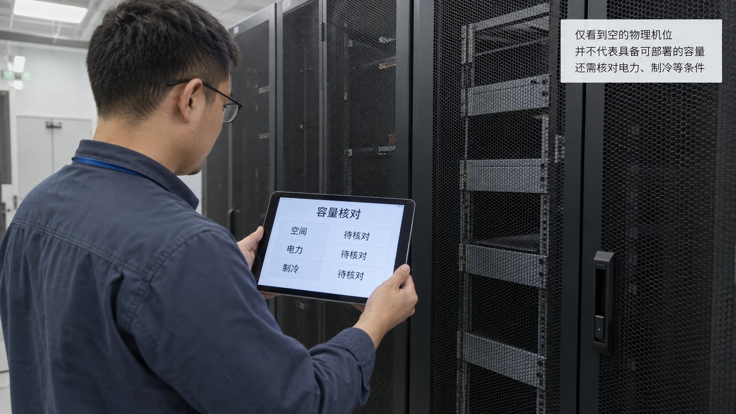
Space capacity asks how many racks and rack units remain. Power capacity asks about current load and remaining redundancy. Cooling capacity asks whether regional heat load and cooling resources are matched. Capacity pages should drill down from site to room, row and rack, with calculation rules and data timestamps.
A PUE page should define the metering boundaries for total facility energy and IT equipment energy, collection interval, treatment of missing data and reporting period. Do not compare a live figure, a daily cumulative result and a monthly total as though they used the same scope. Energy views may also relate outdoor conditions, cooling and load, but correlated curves alone do not establish why energy use changed.
A visualization should locate an alarm at its device, rack and room, then link acknowledgement, assignment, action, review and closure. Device installation, removal, relocation, maintenance and configuration changes also need a timeline; otherwise historical capacity and alarms are hard to explain.
“Integrate DCIM, CMDB, BMS and EPMS” is not enough to guide implementation. For each object type, record its authoritative source, primary key, parent object, field units, collection timestamp, update frequency, validity status, read permissions and fallback on failure. Asset names and business ownership might come from CMDB, rack space and allocation from DCIM, and electricity and power from the metering or distribution system. If one field has several sources, agree on source precedence instead of letting the last update overwrite the authoritative value.
Object relationships need versions too. When a device moves racks, a circuit changes or a sensor is renamed, current location and historical alarms should not be forced into one static link. Synchronize master data on changes, update live sensor points on their collection cycle, and connect them by effective time on the page. This protects alarm location and historical review better than merely adding more APIs.
| Data object | Suggested authoritative source | Responsibility fields to record | Acceptance evidence |
|---|---|---|---|
| Site, room, rack and rack unit | Approved spatial master data or DCIM. | Object key, parent, location, capacity, effective time and maintainer. | Spatial inventory, model mapping, before/after relocation check and version record. |
| Device asset and business ownership | CMDB, asset register or designated business system. | Asset ID, device type, responsible organization, status and source precedence. | Sampled asset reconciliation, conflict list and owner approval. |
| Power, cooling and environmental sensor points | EPMS, BMS, environmental monitoring or approved metering system. | Point ID, unit, timestamp, quality state, update frequency and error representation. | Source comparison, disconnection test, quality state and recovery record. |
| Alarms, work orders and changes | Alarm platform, work-order system and approved change records. | Event ID, object, severity, owner, timeline and closure state. | End-to-end event test, logs, action attachments and review record. |
| Capacity and energy results | Approved calculation rules and corresponding raw data. | Metering boundary, reporting period, formula version, missing-data rule and reviewer. | Raw cumulative readings, recalculation sheet, exception note and approval record. |
The table is a data responsibility checklist prepared by Beijing Hongshan Technology Co., Ltd. for data center visualization projects. It is not a quotation from the energy standards below about DCIM, CMDB, BMS or EPMS responsibilities. The project owner should confirm authoritative sources and division of work against existing systems.
Available capacity is not simply nameplate capacity minus current load. Account for allocated-but-unused space, reserved redundancy, equipment out for maintenance and different power-service constraints. Energy metrics such as PUE should retain meter points, raw cumulative readings, reporting periods, missing-data rules and calculation versions. An unexpected result must be traceable to raw data, not just displayed as an unexplained number.
Collect room floor plans, rack layouts, asset registers, system inventories, point lists, alarm rules, capacity definitions, energy metering relationships, work-order flows and permission roles. At acceptance, verify object location, data timestamps, offline states, alarm links, capacity calculations, PUE scope, permissions and audit logs. Test model loading and page responsiveness on target devices.
Start with the data center solution to define space and integration boundaries, then check the materials, permissions and model acceptance requirements for the digital twin.
Continue listing drawings, models, devices, sensor points, APIs and deployment conditions.
Check least-privilege access to room assets, video, people and operations data.
Learn how to control and accept performance for large room and rack models.