Parks, factories and ports
A 3D scene for areas, buildings, equipment, yards, production lines and key points.
Digital twins
Put a 3D scene, equipment status and business data in one view, for lookup, location and alarm linkage.
Beijing Hongshan Technology maps 3D space, asset points, business data and the alarm process for different industries, and organizes delivery around model lightweighting, linkage rules, the deployment environment and performance acceptance.When a model, an interface or a development team already exists, the scope of model cleanup, 3D interaction and data linkage, and the split of materials, interfaces and acceptance, can be agreed to what is actually needed.
See how it is done in examples such asmapping warehouse tasks to 3D objectsandsplitting a process flow from a spatial view, or provide material for another scene to be assessed.
A 3D scene is more useful when the project must show buildings, areas, equipment location and where an event is. If the core is operating indicators, trends and rankings, an ordinarydata dashboardis usually more direct. Hongshan Technology judges the form from the users, the data conditions and the acceptance goal.
A 3D scene for areas, buildings, equipment, yards, production lines and key points.
Status, alarms, energy, output or operating indicators shown in the scene.
For investment, a showroom, acceptance and a management briefing, so viewers understand the project quickly.
The clearer the material before development, the easier it is to control the modeling scope, precision, schedule and later revision cost.
Scroll the table sideways to see the full comparison.
| Material | Use | How to prepare it |
|---|---|---|
| Plans / CAD / site plan | Confirm buildings, roads, equipment areas, pipes or area boundaries. | Prefer a version that can be dimensioned and marked, so the modeling scope can be confirmed. |
| Site photos / video | Restore materials, color, equipment appearance and the real spatial relationship. | Cover the entrance, key equipment, a panorama, detail and more than one direction. |
| Existing models | Reuse BIM, SketchUp, FBX, OBJ, GLB and similar assets. | Assess polygon count, materials, coordinates, copyright and whether the model can load on the web. |
| Equipment point list | Bind status, alarms, energy, output, temperature and humidity and other business data. | Include the equipment ID, name, area, coordinates, status fields and the data source. |
| Display goal | Decide among a light display, data overlay, alarm linkage or a full platform. | State the users, screen size, briefing setting and what acceptance focuses on. |
When preparing joint-test material, use thedigital twin asset and protocol compatibility matrixto check versions, conversion, permissions and performance for models, maps, video, equipment protocols and business interfaces in the target environment, then theobject, asset, point and page mapping tableto align model parts, the asset ledger, interface fields and page linkage.
The key is not the model itself. It is a stable link among spatial objects, equipment points, business indicators and alarm events.
Link an equipment ID, area, coordinates and the model object, so a click can show status, indicators, history and alarms.
Place ECharts charts, indicator cards, rankings, trends and alarm lists beside a Three.js, WebGL or Cesium scene.
When an API, WebSocket or MQTT reports an exception, the model can highlight, the camera can move, and a popup, alarm list and handling flow can open.
Companies need different depths of “3D visualization.” Hongshan Technology sets the level from the display goal, model material, data sources and how it will be used, so form does not add cost that is not needed.
Scroll the table sideways to see the full comparison.
| Type | Main content | Projects it fits |
|---|---|---|
| Light 3D display | Show a park, factory, port, equipment or showroom, with basic camera changes. | Investment display, a briefing, a project introduction and acceptance display. |
| 3D data overlay | Indicator cards, charts, status marks and point detail in the scene. | Energy, equipment, production, park operations and asset management. |
| Alarm linkage | Model highlight, location, alarm list, popup detail and handling status together. | Security, emergency, equipment maintenance, an energy station and a command room. |
| Digital twin platform | 3D scene, business systems, data interfaces, permissions, back office and maintenance process together. | Projects that need long-term operation, several users, system integration and continued iteration. |
A 3D visualization system is often built with Three.js, WebGL, Cesium, ECharts, WebSocket, APIs and a back-office service. The choice depends on scene scale, model complexity, whether a map is needed, refresh frequency and the deployment environment. Comparethe conditions for Web 3D, Cesium, Unity and Unrealfirst, then test a representative scene.
Suits parks, factories, equipment, showrooms and custom 3D scenes, with control of the model, materials, interaction and motion.
Suits GIS, city scale, a map base, geographic coordinates and a wide area.
The team can develop with Unity and Unreal Engine. An existing project is checked for version, models and plugin dependencies before a client or browser route is chosen. For an Unreal scene and streaming, seeUE5 digital twin development.
Suits indicator charts, trends, rankings, status, alarms and data from a business system.
The project should match models, spatial objects, equipment points, interface fields, linkage rules and the target device, so a demonstration screen is not the only sign that the work is done.
Scroll the table sideways to see the full comparison.
| What is accepted | Boundary that must be explicit | Record that can be checked |
|---|---|---|
| Objects and points | How model parts, asset IDs, GIS coordinates, equipment points, pages and data fields correspond. | An object, asset and point map, sample-check results and a list of items not yet bound. |
| Model lightweighting | Model version, scope, hierarchy, polygon count and texture strategy, and which detail can be removed or must stay. | A model list, the converted version, the size of loaded resources and a record of a representative scene. |
| Alarm and video linkage | Trigger, recovery, de-duplication, location, popup, video permission and how an exception is degraded. | Linkage cases, trigger records, failure scenes and the recovery result. |
| Performance on the target device | Browser, graphics, resolution, network, model scale, concurrency and long-running conditions. | Load, frame rate, interaction, refresh and stability tests on the final device. |
| Private deployment | Server, rendering method, interface network, domain certificate, access control, backup and rollback. | Deployment record, configuration list, account handover and a restore check. |
| Delivery and maintenance | The scope of source or the deployment package, model source files, interface documents, known issues and maintenance responsibility. | A version list, an acceptance matrix, closed issues and the later response agreement. |
Early in the project, fill in theobject, asset, point and page mapping table. In testing, keep evidence against the3D project acceptance checklist.
Industry pages list the object range, common indicators, data sources and the delivery boundary, for an early judgment of whether a 3D scene is needed. Thepark, factory and port comparisoncan be read first. To operate a 3D screen, open thewastewater treatment live demo. The demo uses sample data and is not connected to production equipment.
Link the site, workshops, lines, equipment, production data and work-order alarms.
Buildings, tenant companies, equipment, energy, security and property operations in one view.
Link treatment structures, the process, equipment status, water quality, chemical use and alarms.
Mine space, extraction and haulage, vehicles and equipment, people and risk.
Link BIM floors, HVAC, lighting, elevators, security, energy and work orders.
Risk monitoring and event handling for gas, water supply and drainage, bridges and underground pipes.
Link rooms, racks, rack-unit assets, capacity, power, cooling, alarms and work orders.
Link tunnel sections, structural points, defects, inspections, risk warnings and maintenance tasks.
The first phase can take one representative area or piece of equipment, confirm that a model object can be linked to data by a stable ID, and complete viewing, location and a status change in the target environment. Record the model scope, how data updates and the device conditions before judging the cost of a larger scene.
Scroll the table sideways to see the full comparison.
| Order of confirmation | What to prepare | What the discussion should produce |
|---|---|---|
| Space and model | Area boundary, model source, precision and object IDs | Confirm whether the assets can be used and what modeling still has to be added |
| Data and linkage | Point list, interfaces, status, alarms and the linkage target | Check that objects and points correspond, and how an exception is shown |
| Device and scope | Browser, hardware, resolution, network and how it is used | Record load, operation and performance under the target conditions |
Read how a dashboard pilot scope is acceptedand prepare material with the object, point and page mapping table.
Whether an existing model fits the target device, whether objects can match points, and whether interfaces are usable all change the work of model cleanup, data access and linkage. State the spatial range, the data chain and the environment before a quote.
It can prove model loading, object location, point binding, data updates and the agreed alarm linkage. Expanding to more areas still needs a check of model complexity, data scale and device performance. A small-area test cannot be copied as-is.
A 3D scene can confirm the spatial expression. If the scope includes equipment data, alarms or business linkage, object IDs, interface fields, status changes and exception recovery should also be checked, and those results recorded separately.
A project decides whether 3D is needed from the display goal, then confirms modeling precision, how data is connected and how complex the interaction is.
Projects with a clear spatial structure, equipment points, operating data and a display goal, such as a park, factory, port, energy station, showroom, security command or emergency management.
Plans, CAD, site photos, an equipment list, a point list, existing models and the display goal. The more complete the material, the easier the modeling scope and schedule are to control.
Not necessarily. A project can start with a 3D display and static data, or connect an API, a database, WebSocket, MQTT or equipment data. How live it is depends on the business goal and the data conditions.
Three.js suits a custom 3D scene, equipment and indoor or outdoor space. Cesium suits maps, geographic coordinates, city scale and a wide area.
If the core is indicators and trends, an ordinary dashboard may be more efficient. If the project must express space, equipment location, area relationships and site status, a digital twin is more useful.
Yes. Private deployment needs the server graphics and browser, the size of model resources, interface permissions, the domain certificate, access control and operations responsibility confirmed in advance.
Agree the target browser, graphics, resolution, model scale and network first, then check first load, frame rate, interaction response, interface refresh, alarm and video linkage and long running on the final device. A single number outside that environment is not enough.
BIM mainly carries the model and engineering information of a building or facility. A digital twin emphasizes a continuing link among the model, GIS, equipment points, live data, alarms and the business process. An existing BIM model can be a 3D asset, but lightweighting, object codes and data binding still have to be assessed.
Mainly the modeling scope and precision, the quality of existing models, whether data interfaces are ready, linkage rules, target-device performance, the deployment environment and the acceptance requirements. Confirming the object list, point list and key scenes first usually makes a reliable schedule easier.
Within the contract, front-end and back-end source or a deployment package, models and converted versions, textures, the object and point map, interface documents, deployment notes, test records and operating instructions can be delivered. The boundary is confirmed in the startup and acceptance lists.
Where a digital twin applies Digital twin technology selection Model lightweighting and performance checklist
Project case
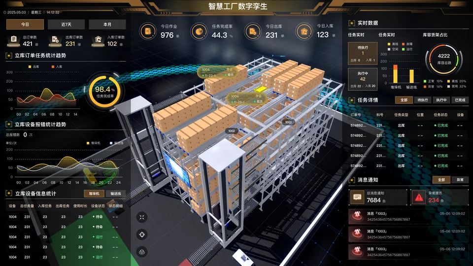
A 3D warehouse, order tasks and equipment exceptions in one view, for watching the work and talking about the site.
View the project